Drivers Wonde Proud Port Devices
CAN bus in a few sentences
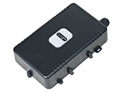
- 37 units of Wonde Proud VT350 device type are connected to Wialon Data Center. This represents 0% of all AVL Hardware connected. This represents 0% of all AVL Hardware connected. Below chart represents the dynamic of connections in the last 30 days.
- The USB 3.0 might be one o those two device that's missing the driver. Can you follow this step to get the Hardware ID and post the ID's back here. Open Device Manager. Under Device Manager Right-click on your Unknown Device and choose Properties. Then like on the photo. Click Details Tab. Click on the dropdown and Choose Hardware Ids.
E-log by EyeRide provides you with FMCSA compliant electronic logging devices (ELDs). Our proprietary technology allows drivers and fleet managers to easily track and manage Records of Duty.

In a broad sense, CAN-bus (Controller Area Network-bus) is actually a set of standards that enable different devices to communicate with each other. It is an asynchronous (time-shifted) serial bus system, developed in 1983 by Robert Bosch GmbH with a goal to interconnect electronic control units (ECU) in motor vehicles.
CAN was divided into various layers, following the ISO/OSI model to achieve flexibility and design transparency. For communication on practice, CAN bus uses two dedicated wires: CAN low and CAN high, by means of which CAN controller is connected to all the network components. CAN allows to substitute quite complex wiring with a two-wire bus. CAN uses a differential signal, that makes it more noise resistant, with two logic states: recessive and dominant. Nowadays CAN bus used pretty much all the way from coffee machines to fleet management and space applications. We briefly describe CAN bus working principles further in this post.

CAN bus: some principles behind
The ISO-11898: 2003 CAN communications protocol explains how information is passed between devices on a network based on an Open Systems Interconnection (OSI) model that is presented as a set of layers on a figure below. The lowest two layers of the seven layer OSI/ISO model are the physical and data link layers. The physical layer defines communication between devices connected by the physical medium.
The Data-Link Layer among other things also takes care of organizing bits into frames and includes two protocols: classical CAN (first use backdated to 1988) and CAN FD (launched in 2012).
Application layer is essentially an end-user layer and provides access to network resources. There are two types of message/frames formats: standard and extended. They differ from each other just by the length of the identifier – a standard one is 11 bits, while extended one is 29 bits.
A standard message structure could be divided on 8 parts as shown on the figure below. Those parts are: Start of Frame (SOF – the start of frame transmission), CAN-ID (frame identifier, message priority identification), Remote Transmission Request (RTR, indicates whether a node requests data from another node or sends data), Control (informs the length of the data in bytes), Data (actual data values than needed to be scaled/converted), The Cyclic Redundancy Check (CRC, ensuring data integrity), ACK (acknowledge, indicates if data correctly being received) and EOF (End of Frame) that labels the end of CAN message/frame.
CAN bus utilize an inverted form of logic with two states: dominant and recessive. Figure above demonstrates a simplified input-output diagram of a CAN transceiver: bit stream going to/from a CAN controller and/or microcontroller. When the controller sends a stream of bits, these are complemented and placed on the CANH line.
The CANL line is always the complement of CANH. CAN must monitor both what is currently on the bus and what it is sending. For applications, both ends of the CAN bus must be terminated since any node on the bus may transmit data.

Each end of the link has a termination resistor equal to the characteristic impedance of the cable. Usually the recommended value for the termination resistors is 120 Ω (in a range 100 Ω – 130 Ω). There should be no more than two terminating resistors in the network, since additional terminations place extra load on the drivers.
Wiring up…
Figure below shows a CAN test bus. The nodes in figure could in principle be sending messages from smart sensing technology and a motor controller. A typical application could be for instance some temperature sensor.
Drivers Wonde Proud Port Devices List
If another sensor node needs to send a message simultaneously, arbitration ensures that the message is sent. For instance, node A finishes sending its message as nodes B and C acknowledge a correct message being received. Nodes B and C on their turn begin arbitration and if node C wins the arbitration then it sends a message. Nodes A and B acknowledge message from node C, and node B then continues on with its message.

The opposite polarity of the driver input and output on the bus should be kept in mind. The CAN bus nowadays widely distributed in cars. It is present in pretty much all the vehicles being made. Cars in a modern world are essentially a global market product, so all vehicles tend to have a CAN bus. The CAN bus is accessed via the OBD port, that is shown on a figure below alongside with an example of a 120Ω termination resistor, soldered onto the DB9 connector with the CAN wiring, located in the DB9 shell housing.
For wiring the OBD port to a CAN DB9 device one needs a cable that can be either purchased or made. To get yourself a self-made one, a 9-pin D-sub socket (female) and an OBD plug (male) are required. The DB9 socket should match the plug for the CAN device.
An example of OBD plug to DB9 CAN wiring including optional termination resistor also shown on schematics below.
To build a sensor network, interface to a CAN bus, and view the CAN signals from vehicles there are a plenty of options. Various microcontrollers currently have the CAN protocol support and could be interfaced to CAN via a CAN transceiver chip.
Also solutions like Raspberry Pi, Texas Instruments Launchpad and Arduino are around and can interface to CAN by means of some add-ons. CAN communication network in modern vehicles could provide a huge data volume that can be utilized in fleet management to increase driver safety, reduce overall expenses, improve maintenance processes and support environmental responsibility.
Enabling CAN bus data provides fleet owners various opportunities to access various information including fuel consumption, odometer readings, revolutions per minute, throttle position, engine load/torque, engine temperature and fuel level.
Some alternatives to CAN protocol include Wireless CAN interfaces, FlexRay and Automotive Ethernet protocols. All of them are currently undergo developing and attract significant attention.
Drivers Wonde Proud Port Devices Download
CAN-bus (Controller Area Network-bus) is a set of standards that enable different devices to communicate with each other. For communication on practice, CAN bus uses two dedicated wires: CAN low and CAN high, by means of which CAN controller is connected to all the network components. CAN allows to substitute quite complex wiring with a two-wire bus. CAN communication network in modern vehicles could provide a huge data volume that can be utilized in fleet management to increase driver safety, reduce overall expenses, improve maintenance processes and support environmental responsibility. Some alternatives to CAN protocol include Wireless CAN interfaces, FlexRay and Automotive Ethernet protocols.
References
Drivers Wonde Proud Port Devices Online
- www.instructables.com/id/How-to-Hack-and-Upgrade-Your-Car-Using-CAN-Bus
- Introduction to the Controller Area Network (CAN), Texas Instruments, 2016.
- www.kmpdrivetrain.com/paddleshift/practical-tips-can-bus
- news.voyage.auto/an-introduction-to-the-can-bus-how-to-programmatically-control-a-car-f1b18be4f377
- www.inventure-automotive.com/glossary/can-bus-communication
- www.csselectronics.com/screen/page/simple-intro-to-can-bus/language/en
- www.csselectronics.com/screen/product/can-bus-logger-canlogger3000
- www.allaboutcircuits.com/technical-articles/introduction-to-can-controller-area-network
- www.axiomatic.com/canbus
- https://canbuskits.com/what.php
- https://tekeye.uk/automotive/can-bus-cable-wiring
- http://autoditex.com/page/can-bus–controller-area-network-34-1.html
- https://artes.esa.int/news/after-decade-development-can-bus-space-flight-ready
- https://medium.com/learn-with-the-lean-programmer/osi-model-layers-explained-ee1d43058c1f
- Controller Area Network (CAN) Bus J1939 Data Acquisition Methods and Parameter Accuracy Assessment Using Nebraska Tractor Test Laboratory Data by Samuel E. Marx. 2015.
- https://coar.risc.anl.gov/can-move-beyond-can-bus-vehicle-networks
