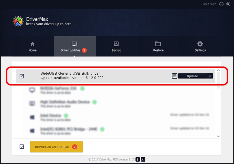
Wideusb USB Devices Driver
Apple Mobile Device Usb Driver free download - USB Audio ASIO Driver, USB Video Device, Apple iTunes, and many more programs. Download usb driver - Best answers Spvd-012.1 usb driver for windows 10 - Forum - Drivers Sony psp usb driver windows 10 - How-To - PSP. No power to the USB device. Ensure that your USB device, such as a camera or USB mouse, has adequate battery power. If you have checked that neither of the above are the cause of your USB problems, the next thing to do is restart your computer. Do not skip this step as it is very often successful in fixing USB Drivers problems.
Introduction
Often the best way to write a USB device driver will be to start withan existing one and modify it as necessary. The information given hereis intended primarily as an outline rather than as a complete guide.
Note: At the time of writing only one USB device driver has beenimplemented. Hence it is possible, perhaps probable, that someportability issues have not yet been addressed. One issueinvolves the different types of transfer, for example the initialtarget hardware had no support for isochronous or interrupt transfers,so additional functionality may be needed to switch between transfertypes. Another issue would be hardware where a given endpoint number,say endpoint 1, could be used for either receiving or transmittingdata, but not both because a single fifo is used. Issues like thesewill have to be resolved as and when additional USB device drivers arewritten.
The Control Endpoint
A USB device driver should provide a single

A USB device cannot be used unless the control endpoint data structureexists. However, the presence of USB hardware in the target processoror board does not guarantee that the application will necessarily wantto use that hardware. To avoid unwanted code or data overheads, thedevice driver can provide a configuration option to determine whetheror not the endpoint 0 data structure is actually provided. A defaultvalue of

The USB device driver is responsible for filling in the
Hardware permitting, the USB device should be inactive until the
Where possible the device driver should detect state changes, such aswhen the connection between host and peripheral is established, andreport these to higher-levelcode via the
Once the connection between host and peripheral has been established,the peripheral must be ready to accept control messages at all times,and must respond to these within certain time constraints. Forexample, the standard set-address control message must be handledwithin 50ms. The USB specification provides more information on theseconstraints. The device driver is responsible for receiving theinitial packet of a control message. This packet will always be eightbytes and should be stored in the
Some control messages will involve further data transfer, not just theinitial packet. The device driver must handle this in accordance withthe USB specification and the buffer management strategy. Thedriver is also responsible for keeping track of whether or not thecontrol operation has succeeded and generating an ACK or STALLhandshake.
The polling support is optional and may not be feasible on allhardware. It is only used in certain specialised environments such asRedBoot. A typical implementation of the polling function would justcheck whether or not an interrupt would have occurred and, if so, callthe same code that the interrupt handler would.
Data Endpoints
In addition to the control endpoint data structure, a USB devicedriver should also provide appropriate dataendpoint data structures. Obviously this is only relevant ifthe USB support generally is desired, that is if the control endpoint isprovided. In addition, higher-level code may not require all theendpoints, so it may be useful to provide configuration options thatcontrol the presence of each endpoint. For example, the intendedapplication might only involve a single transmit endpoint and ofcourse control messages, so supporting receive endpoints might wastememory.
Conceptually, data endpoints are much simpler than the controlendpoint. The device driver has to supply two functions, one fordata transfers and another to control the halted condition. Theseimplement the functionality for
For data transfers, higher-level code will have filled in the
Note: Giving a buffer size of 0 bytes a special meaning is problematicalbecause it prevents transfers of that size. Such transfers are allowedby the USB protocol, consisting of just headers and acknowledgementsand an empty data phase, although rarely useful. A future modificationof the device driver specification will address this issue, althoughcare has to be taken that the functionality remains accessible throughdevtab entries as well as via low-level accesses.
Devtab Entries
For some applications or higher-level packages it may be moreconvenient to use traditional open/read/write I/O calls rather thanthe non-blocking USB I/O calls. To support this the device driver canprovide a devtab entry for each endpoint, for example:
Again care must be taken to avoid name clashes. This can be achievedby having a configuration option to control the base name, with adefault value of e.g.
Because devtab entries are never accessed directly, only indirectly,they would usually be eliminated by the linker. To avoid this thedevtab entries should normally be defined in a separate source filewhich ends up the special library
Not all applications or higher-level packages will want to use thedevtab entries and the blocking I/O facilities. It may be appropriatefor the device driver to provide additional configuration options thatcontrol whether or not any or all of the devtab entries should beprovided, to avoid unnecessary memory overheads.
Interrupt Handling
A typical USB device driver will need to service interrupts for all ofthe endpoints and possibly for additional USB events such as enteringor leaving suspended mode. Usually these interrupts need not beserviced directly by the ISR. Instead, they can be left to a DSR. Ifthe peripheral is not able to accept or send another packet just yet,the hardware will generate a NAK and the host will just retry a littlebit later. If high throughput is required then it may be desirable tohandle the bulk transfer protocol largely at ISR level, that is takecare of each packet in the ISR and only activate the DSR once thewhole transfer has completed.
Control messages may involve invoking arbitrary callback functions inhigher-level code. This should normally happen at DSR level. Doing itat ISR level could seriously affect the system's interrupt latency andimpose unacceptable constraints on what operations can be performed bythose callbacks. If the device driver requires a thread anyway then itmay be appropriate to use this thread for invoking the callbacks, butusually it is not worthwhile to add a new thread to the system justfor this; higher-level code is expected to write callbacks thatfunction sensibly at DSR level. Much the same applies to thecompletion functions associated with data transfers. These should alsobe invoked at DSR or thread level.
Support for USB Testing
Optionally a USB device driver can provide support for theUSB test software. This requiresdefining a number of additional data structures, allowing thegeneric test code to work out just what the hardware is capable of andhence what testing can be performed.
The key data structure is

This specifies the type of endpoint and should be one of

This identifies the number that should be used by the host to address this endpoint. For a control endpoint it should be 0. For other types of endpoints it should be between 1 and 15.
For control endpoints this field is irrelevant. For other types of endpoint it should be either
This should be a pointer to the appropriate
If the endpoint also has an entry in the system's device table then this field should give the corresponding string, for example
This indicates the smallest transfer size that the hardware can support on this endpoint. Typically this will be one.
Note: Strictly speaking a minimum size of one is not quite right since it is valid for a USB transfer to involve zero bytes, in other words a transfer that involves just headers and acknowledgements and an empty data phase, and that should be tested as well. However current device drivers interpret a transfer size of 0 as special, so that would have to be resolved first.
Similarly, this specifies the largest transfer size. For control endpoints the USB protocol uses only two bytes to hold the transfer length, so there is an upper bound of 65535 bytes. In practice it is very unlikely that any control transfers would ever need to be this large, and in fact such transfers would take a long time and probably violate timing constraints. For other types of endpoint any of the protocol, the hardware, or the device driver may impose size limits. For example a given device driver might be unable to cope with transfers larger than 65535 bytes. If it should be possible to transfer arbitrary amounts of data then a value of
Wideusb USB Devices Driver
This field is needed on some hardware where it is impossible to send packets of a certain size. For example the hardware may be incapable of sending an empty bulk packet to terminate a transfer that is an exact multiple of the 64-byte bulk packet size. Instead the driver has to do some padding and send an extra byte, and the host has to be prepared to receive this extra byte. Such a driver should specify a value of
A better solution would be for the device driver to supply a fragment of Tcl code that would adjust the receive buffer size only when necessary, rather than for every transfer. Forcing receive padding on all transfers when only certain transfers will actually be padded reduces the accuracy of certain tests.
On some hardware data transfers may need to be aligned to certain boundaries, for example a word boundary or a cacheline boundary. Although in theory device drivers could hide such alignment restrictions from higher-level code by having their own buffers and performing appropriate copying, that would be expensive in terms of both memory and cpu cycles. Instead the generic testing code will align any buffers passed to the device driver to the specified boundary. For example, if the driver requires that buffers be aligned to a word boundary then it should specify an alignment value of 4.
The device driver should provide an array of these structures
Wideusb Usb Devices Driver Vga
Note: The use of a single array
Usb C To Usb Adapter
